產品資訊
產品資訊
Particulars瞬態電流技術系統Compact TCT System
產品型號:
廠牌名稱: Alibava
Compact TCT is a fully functional Transient Current Technique for material studies. It is intended for studying pad detectors or similar structures with size of the structure of about the size of the laser beam – few mm. Although it is a portable device, its state-of-the-art performance makes it suitable/ready for any kind of material research on difference semiconductors with appropriate band gap such as silicon or silicon-carbide. In addition, the device is useable for educational purposes where a large variety of different semiconductor properties can be studied which we not long ago considered a top notch in scientific research.


產品特點
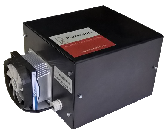
Classic TCT comes incorporates all necessary components in an experimental box with approximate dimensions of 30x30x30 cm3. It incorporates all necessary pieces: Bias-T, wide band current amplifier and laser with the driver. The samples are mounted on the Pelier cooled surface with large powerful fan for the heat sink, which allows for studies in relatively large temperature range.
-
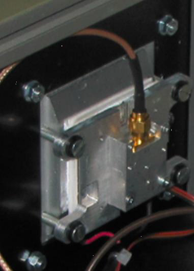
BIAS-T
Bias-T is a decoupling circuit (see above) with three connections: RF for connection to the amplifier IN, RF+DC for connection to the investigated sample and DC for connection to source of HV. The Bias-T is rotated in such a way that the DC contact is accessible at the chassis back. Please make sure that you don’t connect HV bias to the output of the amplifier which is next to it.
-
AMPLIFIER
Wide band amplifier has three connectors (outputs are two with different amplifications, where only one is operational): OUT, IN and POWER. The latter is connected to the connector at the chassis while OUT is also accessible at the chassis back.
-
LASER
Laser is mounted inside the box with its back-side accessible also at the chassis back. The connections are the following.
INTRODUCTION
Particulars lasers are very compact and lightweight since they combine the laser head and driver in the single housing. They were designed for Transient Current Technique, but their applicability is far broader. They offer short pulses (350-4000 ps) with pulses energy corresponding to creation of e-h pairs in silicon equivalent to up to 1000 m.i.p. The lasers can be triggered internally triggers or externally. Internal triggering can be simple with a fixed frequency or a pattern of pulses can be programed with trigger(s) provided independently of the laser/driver pulses.
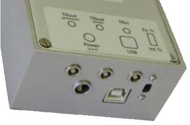
CONNECTIONS
USB – communication with PC
TRout (driver) – trigger output connected to the circuitry triggering the laser diode)
TROut (processor) – trigger output connected to the microcontroller independently on driver (see software manuals for details about the usage of laser in this operation mode)
TRin – trigger input for external triggering of the laser pulse. Note that in this mode the switch for selection of the operation mode should be in “Ex. Tr.” (External trigger).
Ex. Tr./Int. Tr. – external / internal triggering of the laser
Power – 2 pole lemo connector for power supply
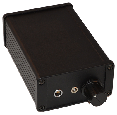
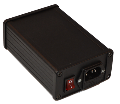
POWER SUPPLY
Only Particulars power supply should be used to power the lasers. At the moment they are designed to be operated only at 220V/50 Hz (AC). A two pin Lemo connector is used to deliver the power to the laser.
LASER HEADS
The laser can have two different outputs:
- a focused and collimated head
- a fibre coupled head (single mode) output using standard FC connector
While fibre connection should be used with optical system, focused-collimated head can be used to directly illuminated device. The collimator can be moved for few mm backward and forward in order to achieve desired collimation. Use the screw on top of the head and slide the collimator for desired position.
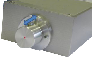
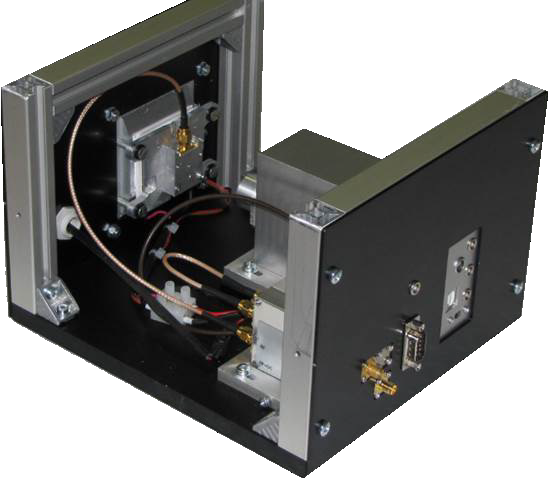
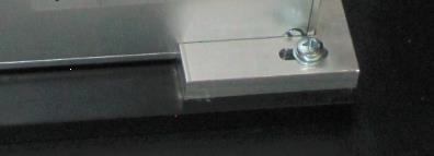
MOUNTING PLANE
Mounting plane has approximate size of 5×5 cm2 with different options for attaching the box with the detector (see www for details). Laser is mounted in the way that it hits approximately the center of the detector box. The mounting plane can be moved in vertical and horizontal direction for few mm in order to allow for better alignment with the center of the laser beam. To do it lose the screws (red circles for vertical and green circles for horizontal movement in below figure) and slide the mounting plane in the desired position. The mounting plane is cooled by Peltier (80 W) which allows for reaching the temperature difference (room temperature – sample temperature) of around 30oC. The back side of Peltier is cooled by a fan. The temperature sensor (Pt-100) is mounted at the side of the cold plate.
Beware: there can be a systematic offset at the place of the sample and the point at which temperature is measured.
The power and control lines for the temperature control of the mounting plane (fan power supply, Pt-100 lines and power lines for Peltier cooler) are connected via the D-SUB connector at the back of the experimental box.
Beware: If you set the temperature below the dew point make sure that the lid is closed in order to limit the flow of the moist air around the cold plate/sensor. The condensation formed on the sensor can otherwise lead to potential electrical breakdown.
CONNECTIONS
The back side of the experimental box is show in the figure below.
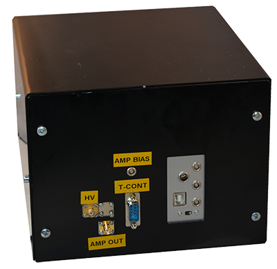
There are four connectors/connector regions at the back:
- Laser connectors (green)
- D-Sub 9 pin – Temperature control connectors (red)
- LEMO – Amplifier bias connector (magenta)
- SMA – Amplifier out (yellow)
- SMA – DC bas voltage in (blue)
Beware: DC bias voltage and amplifier out have the same connector. Make sure that you don’t swap them.
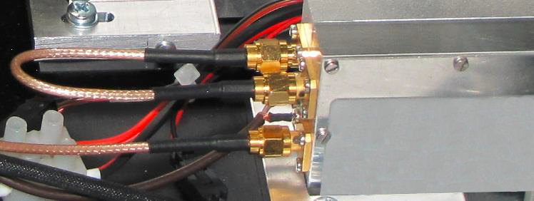
The amplifier (IN) and bias-T (RF) are connected inside the chassis as shown in the figure below. The sample/detector is connected with Bias-T (RF+DC) input with the SMA-SMA cable as shown in the mounting table figure.
Please, disconnect all power sources before reattaching/reconnecting the cables.
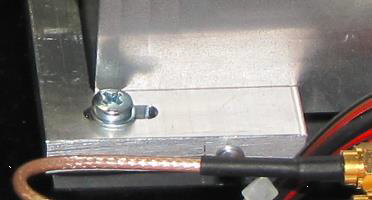
4. Mounting the laser and sample
The laser is brought into the correct position and fixed into it by a bracket which is screwed to the base plate (green circles in below figure). An additional fixation of laser and bracket id done by a single screw (red circle in below figure). When properly fixed the laser will illuminate the center of the mounting plane. It is possible that the beam is not perfectly aligned with the desired illumination spot. Please use the screws to adjust the position of the mounting plane (see section 3).
The sample is mounted on the mounting plane. The particulars housing is ideally suited for that and offers a very good RF shielding. Already two diagonal screws offer a good thermal and electrical contact with the mounting plane. The mounting plane allows for attachment of SMA connectors with sample housing in place.
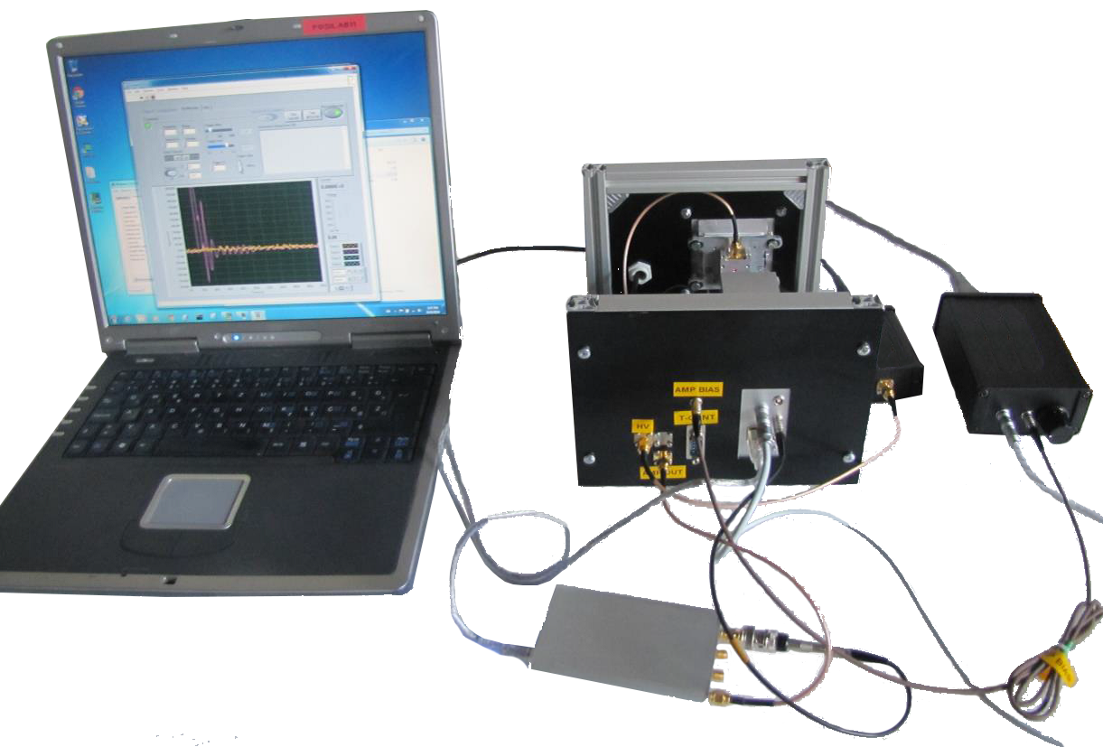
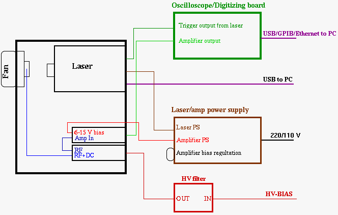
5. Connections outside the box
The output of the amplifier should be connected the oscilloscope, which is provided by the user. The DC connection is usually connected to HV through the bias voltage filter (provided by the Particulars).It has a SMA output and HV BNC connector for the input. Laser power supply comes with an additional power supply for the amplifier. The connection scheme outside the box is shown in the figure below. Here a PSI – DRS digitization board is used as oscilloscope. A schematic view is also shown without temperature control system which is connected via D-Sub connector to the temperature controller at the back. The temperature controller is optional. One can use Peltier contacts of D-Sub connector to connect a regular PS to the Peltier for manual control of the temperature.